The Automated Edge: Designing Robotic Automation Around Edge Based Video Analytics
Key Points at a Glance:
Robotic automation is moving away from centralized decision making toward local intelligence at the edge. When video analytics runs directly on robots and equipment, systems can assess risk, adapt motion, and enforce safety in real time. This blog looks at how designing automation around edge based vision changes control loops, improves reliability, and supports operations that cannot afford delays or downtime. The difference shows up not in demos, but in how these systems behave when conditions stop being predictable.
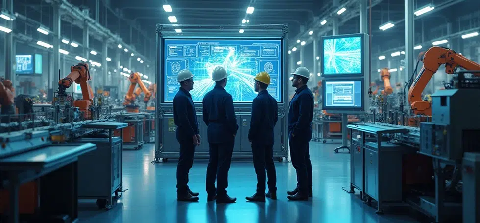
In a busy warehouse, an autonomous robot slows as a forklift cuts across its path. The robot does not stream video to a remote server or wait for instructions from a centralized system. The cameras mounted on the robot process the scene locally. The obstruction is classified, the risk assessed, and a new path is calculated almost instantly. The robot continues its task with no interruption to surrounding operations.
This is not about smarter robots in isolation. It is about how robotic automation systems are now designed, with video analytics running at the edge and tightly coupled to motion, safety, and control.
That coupling is what allows automation systems to respond to real conditions instead of ideal ones.
Several companies have demonstrated what this looks like in practice. By deploying AI camera sensors and real time video analytics across dozens of sites, they have reduced potential safety incidents by more than seventy percent while improving productivity. These results did not come from adding vision as an afterthought. They came from designing automation systems where perception and action happen locally, without depending on cloud round trips or fragile network paths.
Why Edge Based Video Analytics Changes Robotic Automation
Traditional video analytics architectures rely heavily on centralized processing. Video streams are sent upstream, analyzed, and decisions are pushed back downstream. This approach works when timing is flexible and environments are controlled. It struggles in dynamic industrial settings.
Robotic automation systems operate close to people, vehicles, and fast-moving equipment. Delays of even a few hundred milliseconds can turn into safety risks or unnecessary stops. Edge based video analytics addresses this by keeping inference and decision making close to the source. Cameras, robots, and local gateways handle perception and response directly, maintaining tight control loops.
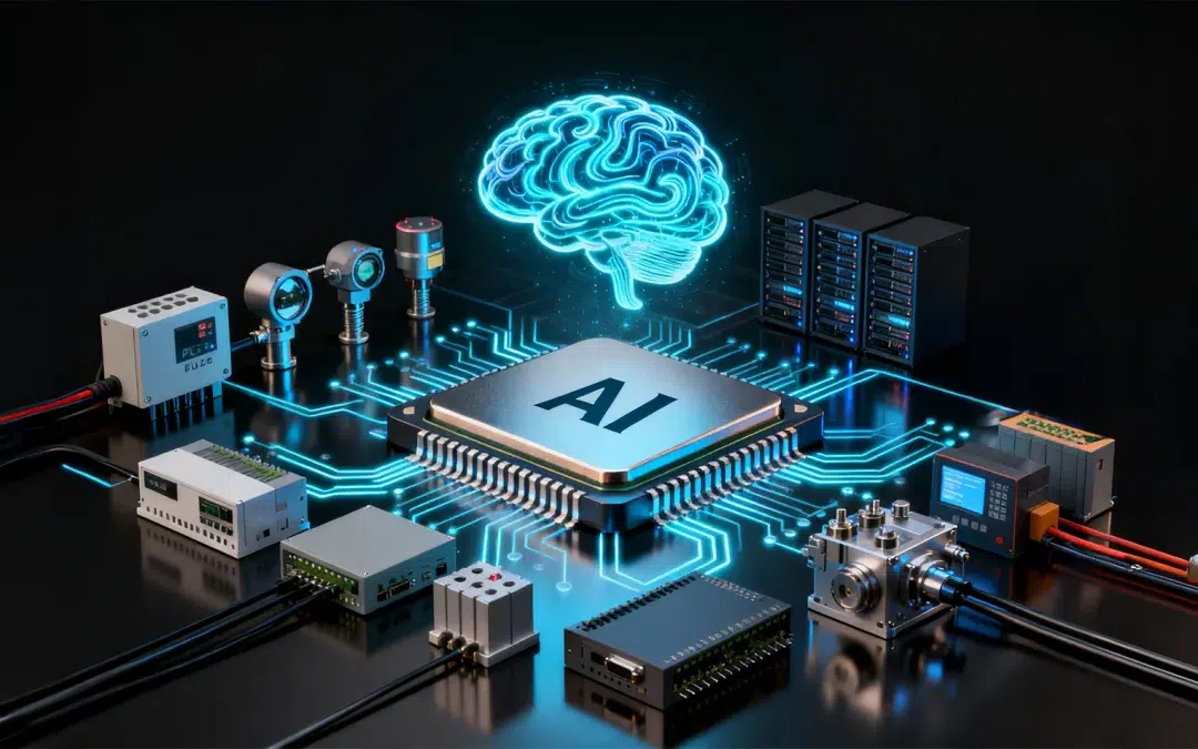
Recent advances in embedded computing have made this approach practical. Platforms such as NVIDIA Jetson and Edge TPU class accelerators allow complex vision models to run within constrained power and thermal envelopes. With newer edge AI modules, real time video analytics can operate continuously on robots and industrial equipment, without relying on constant connectivity to centralized infrastructure.
For robotic automation, this shifts video analytics from a monitoring function to a core control input.
Designing Automation Where Vision and Motion Are One System
In modern robotic automation, vision is no longer a peripheral component bolted onto an existing workflow. It directly influences how robots move, how safety is enforced, and how tasks are executed.
Consider autonomous mobile robots in warehouses. Navigation is not based solely on predefined maps or fixed markers. Vision and LiDAR work together to interpret changing layouts, temporary obstructions, and human activity. Edge based analytics monitor proximity zones and trigger immediate responses when safety thresholds are crossed. These decisions need to be deterministic and fast, which is why they stay at the edge.
The same principle applies to fixed automation. Robots performing inspection, assembly, or material handling increasingly rely on visual context to verify steps, identify defects, or adapt to variation. From an engineering perspective, this introduces real constraints. Models must run predictably; latency must be bound; hardware must survive industrial conditions; and these are embedded design problems, not abstract AI challenges.
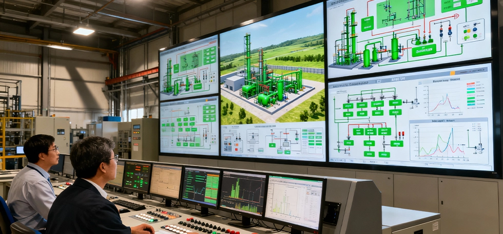
What This Looks Like in Real Operations
In manufacturing environments, robots equipped with edge-based vision systems inspect welds, measure tolerances, and verify assembly sequences as parts move through production. Issues are detected immediately, before downstream processes amplify the cost. Over time, this stabilizes throughput and improves quality without adding manual inspection layers.
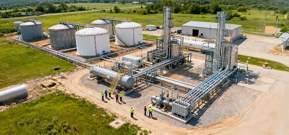
In warehouse and logistics operations, video analytics at the edge supports parcel tracking, conveyor inspection, PPE detection, and occupancy monitoring. Because processing happens locally, these systems continue to function even when connectivity is unreliable. Operators receive alerts with visual context, making it easier to act quickly and accurately.
Across supply chains, edge-based computer vision provides visibility into how space and assets are actually used. Cameras recognize items, read codes, and track movement in near real time, feeding inventory and planning systems without constant human input. This level of visibility depends on reliable embedded pipelines, not just accurate models.
The Architecture Behind Edge Driven Robotic Automation
Most production systems follow a layered architecture, even if it is not always explicitly described.
At the device layer, cameras and sensors are paired with embedded AI accelerators capable of continuous inference. Choices here depend on performance needs, power budgets, and environmental constraints.
The edge processing layer handles sensor fusion and real time decision making. Video data is combined with inputs from LiDAR, depth sensors, and robot telemetry to support navigation, safety, and control. This layer must behave predictably under load.
Above that sits orchestration software that manages devices, models, updates, and policies across fleets. It enables scaling and lifecycle management while keeping time critical behavior local.
Designing this architecture is less about chasing peak performance and more about understanding how systems behave over months and years of operation, with dust, vibration, uneven lighting, and occasional network failures.
Reliability Matters More Than Raw Accuracy
One of the most common mistakes in edge AI deployments is overemphasizing model accuracy while underestimating system behavior. In real environments, sensors drift, lighting changes, and compute resources are shared across tasks.
Robotic automation systems must continue to operate safely and predictably under these conditions. That requires careful selection of cameras, optics, lighting, and compute platforms, along with model optimization and fallback behavior. Anomaly detection and graceful degradation matter as much as inference performance.
This is where embedded engineering discipline becomes critical.
What the Market Shift Is Really Telling Us
Investment in computer vision and AI continues to accelerate, with many organizations allocating a significant share of capital toward these technologies. The important signal is not the growth rate itself. It is the transition from experimentation to core infrastructure.
As vision enabled robotic automation moves into production at scale, expectations around reliability, maintainability, and integration rise sharply. Systems are no longer judged on demos. They are judged on uptime.
Looking Ahead
As edge hardware becomes more capable and energy efficient, robotic automation systems will rely even more on visual feedback to adapt to changing conditions. The boundary between sensing, reasoning, and control will continue to narrow, especially in environments where variability is the norm rather than the exception.
The automated edge is not about speed alone. It is about designing systems where seeing and acting happen within the same control loop, without unnecessary abstraction or dependency on centralized infrastructure.
For teams building automated facilities, the real question is no longer whether to use video analytics. It is whether robotic automation is being designed around edge-based vision from the start, or whether vision is still treated as an add on layered onto legacy control architectures.
That design choice will increasingly define how scalable, safe, and resilient automation systems are over time. If you are evaluating how edge based video analytics fits into your robotic automation roadmap, reach out to us to talk through architectural tradeoffs with teams who work on these systems every day.